Rolled high-tech threads in use
Rolled threads have become an integral part of modern technology. They enable precise movements, reliable connections and fulfill the highest safety requirements - in a wide range of applications, from cable car cabins to high-tech knitting machines. rolled high-tech threads. Immerse yourself in the fascinating world of the Thread rolling!
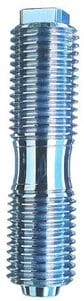
Movement screw vs. Fastening screw
Rolled high-tech threads are mainly used as movement screws in ball screws. They are rarely used as fastening screws. In a screw drive, the thread slides directly on the flanks of the screw spindle. In ball screws, on the other hand, balls serve as low-friction connecting elements. This technology dominates the application today.
In its entirety - screw spindle and nut - the ball screw drive is a roller screw drive with balls as rolling elements. It is used for Conversion of a rotary movement into a straight-line (linear) movement or vice versa. As simple as the basic structure of the ball screw can be described, the designs and practical requirements are just as varied.
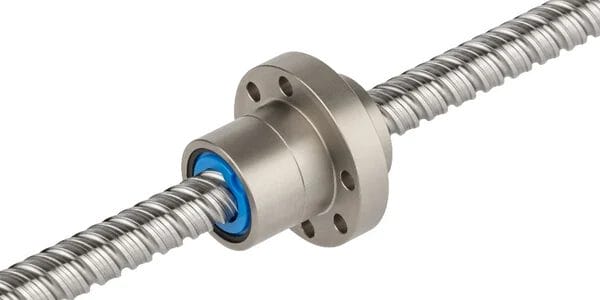
In terms of application, the ball screw offers the designer almost unlimited possibilities for solving transportation and positioning tasks. This ranges from ball screw drives with a driven spindle or driven nut to those with double nuts and ball screw drives with rolled precision spindles.
Ball screw drive for a goods lift
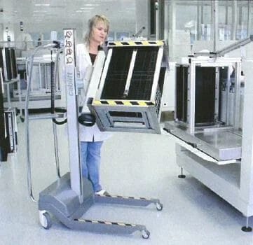
With the load lift shown in Figure 3, loads of up to 100 kg can be moved safely and without fatigue; up to six of the standard crates shown can be transported from the storage rack to the workstation at the touch of a button. Rolled ball screw drives ensure:
- Low wear and tear with high positioning accuracy.
- Compact drive units through reduced mechanical parts.
- High security through precise deflections in the spindle nut.
Ball screw drive for a coffee machine
Figure 4 shows the piston unit of a coffee machine for the catering industry. The plunger, as the central element, is moved up and down by two laterally arranged ball screws with a rolled thread. The advantages are
- Uniform stamping movement: Ensures an optimal aroma.
- Durability and reliability: Thanks to the robust rolled threads.
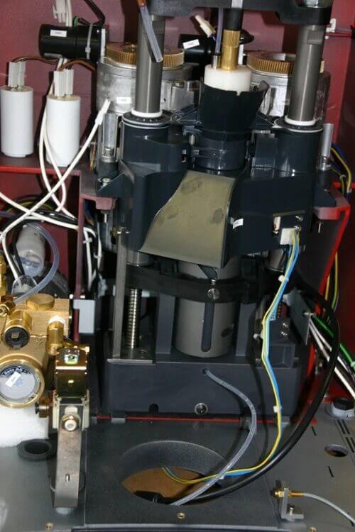
After the grinder has ground the fresh coffee beans to the desired fineness, the required amount of powder enters the brewing chamber through the inlet funnel. At this point, the plunger is at the top. The threaded spindle drives lower the plunger with the required force and the plunger presses the coffee powder together. This must be done extremely evenly: If the coffee layer did not have a homogeneous thickness, the hot water would not flow through it evenly. The aroma would vary from coffee cup to coffee cup, resulting in a loss of quality. After brewing, the filter cake is ejected using a tamping movement.
High-safety thread for the suspension of cable car cabins
Ropeway manufacturers differentiate between reversible aerial tramways (large cabins in shuttle service) and circulating ropeways (many small cabins are coupled into the rope). The cabins of modern ropeways are each suspended from bolts with rolled threads - the experts refer to these as tension rods. These tie rods are high-security components.
In the past, steep track manufacturers made the connections by welding. However, such constructions can no longer meet the now much stricter safety requirements. Welding has also become far too costly due to the associated change in material structure and the prescribed tests.

(Central Swiss Alps) rotates 360° during the journey
The large cabins of the reversible aerial tramway shown in Figure 5 are each suspended from four tie rods. Each of these brackets extends through the cabin to the cabin floor. The cabin floor is attached to these four bolts. The cabin walls and glazing only serve to protect passengers from the weather and unintentional "exit" from the cabin.

rolled threads support the cabin and ensure safety.
The cabin suspension of the orbit shown in Figure 6 is constructed differently. The small cabins also have four rolled threaded bolts, but these do not pass through the cabin as a pull rod. Instead, forged parts with a threaded insert in each corner of the cabin roof accommodate one of the four bolts. These lugs are connected to the cabin floor, which supports the walls and glazing, via corner braces. The force flow here therefore goes from the cabin suspension via the threaded bolts into the ceiling brackets. From there, the force is transferred via four corner profiles into the floor brackets - also forged parts - and thus into the floor structure. Because the corner braces are required as a connection between the suspension and the cabin floor, this is referred to as a self-supporting cabin.
Rolled threads are mandatory for the tie rods of large cabins (Fig. 7). The base material - high-alloy steel with manufacturing certificate - as well as the shape and manufacture of the thread are subject to very strict standards and regulations for the required material tests (X-ray, ultrasound). Approval for installation is only given once the corresponding certificates have been obtained. In this application, tensile strength and notched impact strength are important, as is proof that the parts can still be safely used at temperatures of -20°C. If shaping production is required, this is carried out exclusively by water jet cutting. This is because only cold processing does not cause any structural changes in the material.
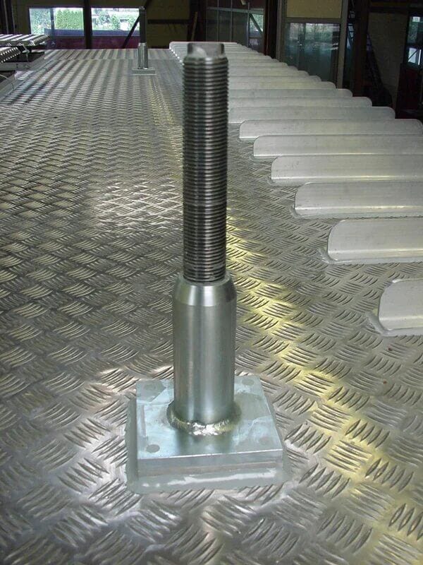
current safety standards for monorail systems
Nowadays, bolts with rolled threads are practically only approved for the suspension of small cabins. Because the longitudinal fibers of the material are not cut during thread rolling, unlike with milling or turning, but only deflected, they meet the requirements for the prescribed crab impact strength. Milled or turned threads do not meet the safety standards.
Silent threaded spindle drive for a swing/sliding door
With up to 200,000 movement cycles per year, sliding swing doors on public transportation are sometimes in use for over 20 years. This requires high-quality components ahead. In the double-leaf swing/sliding door shown in Figure 8, a threaded spindle drive with a rolled thread ensures that the door leaves swing open smoothly and, above all, safely.
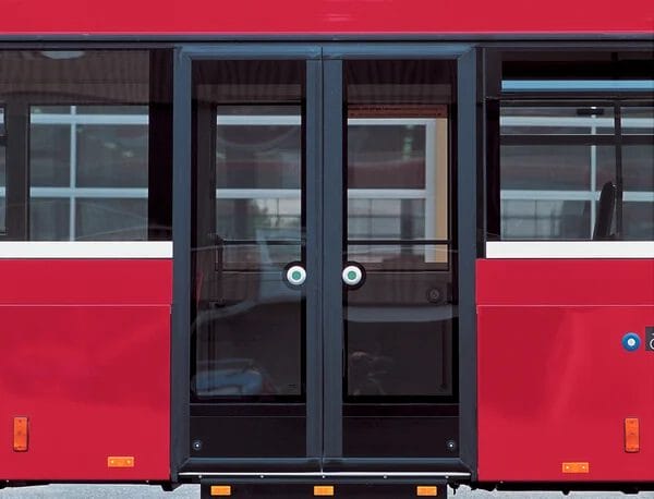
Opening and closing takes place via a longitudinal shaft onto which both a left-hand thread - for the left-hand door leaf - and a right-hand thread - for the right-hand door leaf - have been rolled. The threaded spindle is driven by a DC motor via a toothed belt and a torque limiting clutch.
The two nuts in the carriages (Fig. 9) - one with a left-hand thread, one with a right-hand thread - move on the threaded spindle and thus cause the door leaves to move sideways. Curved guide rails ensure that the door swings outwards or inwards. The door is turned using levers. An axis of rotation is built into the carriage for this purpose.
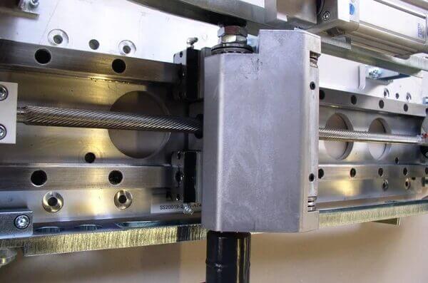
The emergency opening function is of particular importance. Passive safety standards stipulate that the doors must be unlocked both in an emergency and in the event of a system failure and must be easy for passengers to open - even in a panic situation. After pressing the red emergency button, the electric motor is disconnected from the threaded spindle (clutch). The air reservoir - which is permanently pressurized during normal operation - suddenly loses pressure. Once the excess pressure has been released, two strong springs open the door leaves sufficiently to allow them to be pushed open fully by hand.
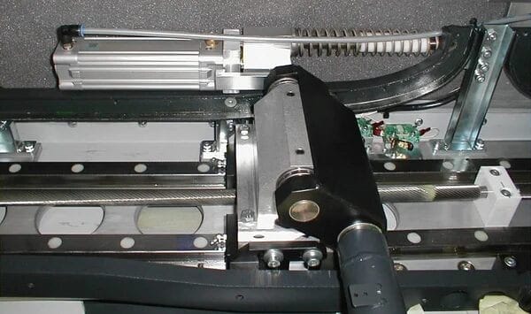
the threaded spindle and the spring for the emergency opening (at the top)
The pitch of the rolled thread is crucial to ensure that the door can be opened manually in an emergency. If the pitch is too small, the door would be self-locking. With the selected pitch of 100 mm, the two nuts can be moved on the threaded spindle with little effort (Fig. 10).
Counter-rotating threaded spindle for a cable assembly device
Before an electrical connection cable can be connected at its ends with plugs or terminals, it must be cut to length and stripped. Today, cables are almost exclusively assembled fully automatically.
The cable assembly device shown in Figure 11 allows cables of different diameters. The insulated cable is fed from the right by a feed roller via a roller system into a guide tube (the swivel guide). The machine stops after a predetermined path. Two blades (one from below and one from above) approach the cable and cut the insulation all the way through. This leaves one end bare. The cable is then pushed further until the required length is reached.
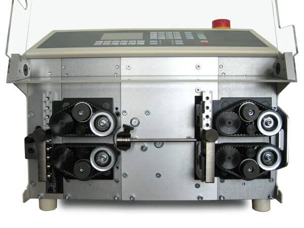
The blades then cut the copper cable all the way through. The insulation is slit open, stripped and falls down. The cut and stripped cable is then placed in a storage container for further processing.
To carry out the vertical cutting movements, the lower blade moves upwards and the upper blade moves downwards. The two blades are fed via a rolled threaded spindle.
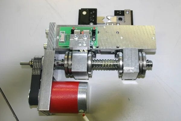
threaded spindle can be clearly seen. They generate the opposite vertical movement via the two nuts.
Movement of the knives (top)
More precisely, the threaded spindle consists of two screwed half-spindles, one with a left-hand thread and the other with a right-hand thread. When the threaded spindle is turned, the two nuts on which the knives sit move in opposite directions (Fig. 12). The screw connection in the center of the spindle does not loosen because the fastening thread is tightened during the cutting process - this is where the large forces occur. The retraction does not exert any force on the screw connection.
Ball screw drive for a telescope
On the Canary Island of La Palma, 2225 m above sea level, there is a telescope developed under the leadership of the Max Planck Institute for Physics (Fig. 13), which can detect gamma rays from galaxies up to eight billion light years away with extremely high sensitivity. With a diameter of 17 m, this telescope is the largest of its kind in the world. The pivoting frame consists of carbon fiber tubes.
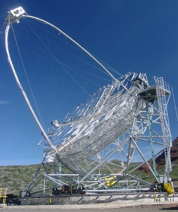
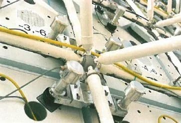
Almost 1000 aluminum mirror segments, mounted on 247 rigid support plates, result in 240 m2 mirror surface. Within 20 seconds, the researchers can align the telescope to any point in the firmament. To do this, each of the carrier plates is set to a pre-aligned laser point by two ball screws (thread with a nominal diameter of 10 mm and a pitch of 2 mm) (Fig. 14). Hybrid stepper motors drive the almost 500 ball screws.
Ball screw drives without play for a knitting machine
The high-tech knitting machine shown in Figure 15 is able to knit precise patterns on huge lengths of fabric using thousands of needles. Just one movement and control unit is used to move the stretched fabric to the left and right and up and down with high speed and precision.
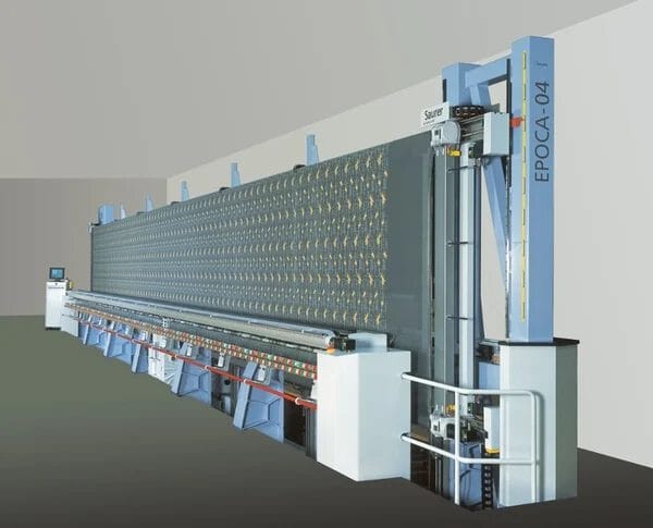
Several factors speak in favor of the ball screw drive: accuracy, simplicity, cost and robustness; this applies in particular to the vertical travel. The ball screw drives with 25 mm nominal diameter of the threaded spindle and 25 mm thread pitch have four ball returns. The "gearbox" is integrated in the nut body (Fig. 16). The rotary movement is converted into a linear movement precisely and backlash-free.
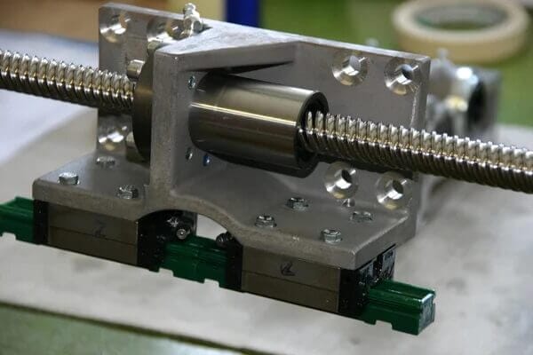
It would not be possible to achieve zero backlash with a standard ball screw over 2 m long, as every nut has a certain amount of play. In most applications, the play is insignificant. In the case of the knitting machine, it would have a devastating effect, especially when reversing the direction of movement. When the nut moves vertically, accelerations greater than the acceleration due to gravity occur. However, as soon as gravity is removed, the nut would flutter on the spindle. But this must not happen.
To eliminate the play, a single nut is used instead of the usual system with two nuts braced against each other, which combines a very short design with high rigidity. The preload is generated via a special thread based on the profile of the Gothic ball screw on the spindle.
Depending on the length of the knitting machine, between three and eleven vertical ball screw drives must be controlled synchronously. The ball screw drives consist of commercially available individual parts that are inexpensive to manufacture. The design, handling and maintenance of the entire drive are simple. Only standard elements are used. Even the linear guides for the ball screws are standardized purchased parts.
To the blog overview
Technical principles of thread rolling
Service provider in development
With state-of-the-art production methods, many years of expertise and our tool inventory of over 1000 rolling tools, we produce rolled threads that meet even the most unusual requirements:
- Gradients up to 6 × diameter
- Spindle lengths up to 6 m
- Spindle diameter from 2 to 160 mm
- All standard profiles (M, Tr, UNC, UNF, UNEF, Whitworth)
- Multi-start threads, also as right/left-hand threads
- Steep thread profiles
- Ball screw profiles
- Special profiles
- Screw profiles (special quality and price advantages!)
- Serrations and knurling
- Conical thread
- Threads on prefabricated and/or bulky parts, e.g. also on forged parts
The 9 blogs contain excerpts from the - Library of Technology -, Volume 286, Thread rolls, included.
This book was compiled with the technical support of Kurt Husistein and published by Verlag Moderne Industrie, ISBN 978-3-937889-30-6.
Literature and sources
Kübler, Karl-Heinz, Mages Walter J. Handbook of high-strength screws, 1st ed. Essen: W. Girardet Buchverlag, 1986.
http://www.hp-gramatke.de: Hans-Peters Mathematical-Technical-AlgorithmicA linguistic smorgasbord.Verein Deutscher Eisenhüttenleute (ed.): Werkstoffkunde Stahl, vol. 1 Berlin: Springer, 1984. Apel, Heinz: Gewindewalzen: Kaltverformen von Präzisionsgewinden und Spindeln, Munich: Hanser 1952.
© 2007 All rights reserved by sv corporate media, D-80992 Munich
Illustrations: No. 1, 23-25 RWT Rollwalztechnik GmbH, Engen; No. 2 Photo Deutsches Museum, Munich; No. 3 Musée du tour automatique et d'histoire de Moutier, Moutier (Switzerland); No. 16 Fette GmbH, Schwarzenbek; No. 18 Meinrad Plaz, Staufen (Switzerland); No. 26 Habegger SA, Court (Switzerland); No. 34-36 FBT Fahrzeug- und Maschinenbau AG, Thörigen (Switzerland); No. 37, 38 Schleuniger AG, Thun (Switzerland); No. 39, 40 Max Planck Institute for Physics (Heisenberg Institute), Munich; No. 41 Saurer AG, Arbon (Switzerland); No. 42 Line Tech AG, Glattbrugg (Switzerland); all others Eichenberger Gewinde AG, Burg (Switzerland). Typesetting: abavo GmbH, D-86807 Buchloe. Printing and binding: Sellier Druck GmbH, D-85354 Freising. Printed in Germany 889030.


