
The thread rolling library 3/9 - Basics and applications
In this blog article you will learn more about the basics and applications of the Thread rolling. You can expect exciting insights into the designations, different types of rolled thread systems and their applications through to the test methods.
What is a thread?
From a physical point of view, a thread is a spiral-shaped inclined plane; a screw and the matching nut represent a sliding combination. The following rule of thumb applies to the use of threads:
- Small incline: For fastenings.
- Larger gradient: For motion applications.
Designations on the thread
The Designation of a thread is made up of several elements:
- Thread profile: The code letter, e.g. "M" for metric standard thread.
- Outer diameter: Nominal size in millimeters.
- Gradient: Z. E.g. 1.5 mm for a metric M10 thread.
One example: M10 refers to a metric standard thread with an outer diameter of 10 mm and a pitch of 1.5 mm. LH stands for a left-hand thread, while the standard designation for right-hand threads is RH is.
The thread systems and their thread profiles described below apply to all known manufacturing methods such as milling, turning, whirling, grinding or rolling. In the case of rolled threads, the manufacturer may modify the standard profile to some extent.
Advantages of thread rolling
The Thread rolls offers several advantages over other manufacturing processes such as milling or turning:
- Stronger surface: No material interruption, resulting in higher strength.
- Efficiency: Less material loss and shorter production times.
- Precision: The flank diameter remains constant even with large quantities.
The importance of the pitch diameter for threads
The Flank diameter of a thread is a decisive dimension that defines the contact area between the screw and nut. The pitch diameter plays a central role in rolled threads:
- Precision: The Flank diameter ensures optimum load distribution.
- Functionality: A precisely rolled thread increases the service life and reduces friction.
Types of rolled thread systems
The three best-known systems for Rolled threads are:
- The metric ISO thread
- The Whitworth thread
- American thread types - the ISO inch thread
In all three thread systems, there are both standard threads and fine threads. Although there is currently no globally standardized thread standard in sight, the thread is considered to be the most comprehensively standardized machine element. In addition to generally applicable standards, there are special "specifications" for motion threads. However, these are usually dependent on the manufacturer.
> Eichenberger screw drives - fast, precise, reliable.
The metric ISO thread (M)
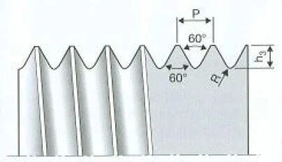
The metric thread is a globally standardized thread with metric dimensions and a 60 degree flank angle (see Fig. 2 Thread profile of the ISO metric thread). The outer edges run together in a wedge shape, which is why it is also called a pointed thread. The "M" stands for metric standard thread, the number behind it indicates the outside diameter in millimetres. The exact definition is defined in DIN 13 and DIN 14. The designation "MF" stands for the metric ISO fine pitch thread, which has a smaller pitch and is used in the watch industry or in measuring instruments, among other things.
Eichenberger's core competence lies in the rolling of threads. Would you also like to have your fine thread rolled? Click here here.
The MJ thread (ISO 5855) is a modification of the metric ISO thread and is used in aerospace technology with an enlarged core diameter and radius at the base of the thread.
The following abbreviations of the metric thread profile apply to the external threads on the bolt.
- D = Nominal diameter (outside diameter)
- P = Pitch
- h3 = 0.61343P (thread depth)
- R = 0.14431P (radius at the thread root)
- R = 0.15...0.18P (for MJ thread)
Whitworth thread
Named after its inventor Sir Josep Whitworth, the Whitworth thread is specified in inches. Unlike the metric ISO thread, the flank angle of the Whitworth thread is 55°.
The thread profile of the Whitworth thread standardized according to British Standard 84 (Fig. 5) can be differentiated into: BSW (British Standard Whitworth; Whitworth standard thread), BSF (British Standard Fine; fine thread) and BSP/G (British Standard Pipe; pipe thread; according to DIN ISO 228 with the designation "G").
The pitch P is calculated from the number of turns per inch specified in the dimension tables. The following rough definition applies to external threads on the bolt.
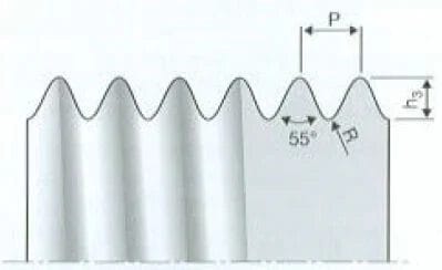
- D = Nominal diameter (outside diameter)
- P = Pitch (specified in practice in gears per inch)
- h3 = 0.64033P (thread depth)
- R = 0.13733P (radius at the thread root)
American thread types - the ISO inch thread
The American ISO inch threads (UST threads according to ASME B 1.1 and B 1.2):
UNC Unified National Coarse (coarse thread), UNF Unified National Fine (fine thread), UNEF Unified National Extra Fine (extra fine thread), US Unified National Special ("free" special thread with additional information) and UNJ Unified National thread series with external thread controlled root radius (ISO inch thread with enlarged core diameter and radius at the thread root), comparable to the MJ thread.
The specifications for the outside diameter and the number of threads given in the dimension tables are based on the unit of length inch (1 inch = 24.4 mm). As with the metric ISO thread, the flank angle is 60°. The profile of the ISO inch thread shown in Figure 6 therefore corresponds to that of the metric ISO thread.
- D = Nominal diameter (outside diameter)
- P = Pitch (specified in practice in gears per inch)
- h3 = 0.61343P (thread depth)
- R = 0.14434P (radius at the thread root)
- R = 0.15...0.18P (for UNJ thread)
Special rolled threads
This section describes other thread profiles that are important for thread rolling: the trapezoidal thread, the round thread and the Gothic ball thread.
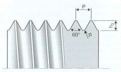
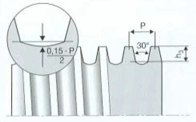
Trapezoidal thread
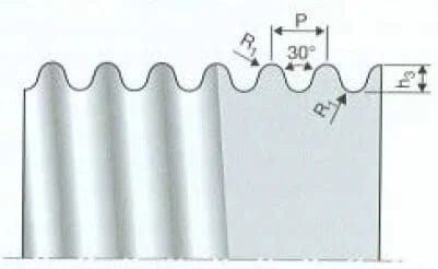
For trapezoidal threads to DIN 103, the nominal diameter and pitch follow the ISO metric thread standard; the thread depth h3 is 0.5P, the flank angle 30° (Fig. 7). For trapezoidal threads to DIN 380 (lower load-bearing depth), the core diameter is increased by 0.4P, otherwise the profile is identical to that to DIN 103. A radius is permitted on the core diameter for thread rolling (P/2 0.15).
The Speedy steep thread spindles from Eichenberger for more power and ultimate speed.
Round thread
Round threads to DIN 405 are particularly suitable for fittings as they are especially resistant to dirt and damage. Fire pipes and hoses, for example, have threads that are insensitive to impact and dirt (Fig. 8). The outside diameter is given in millimeters, the pitch in inches. It is worth noting that the thread of the nut has a different radius to that of the screw.
- D = nominal diameter
- P = Pitch
- h3 = 0.5P (thread depth)
- R1 = 0.238P (same radius on the outside diameter and thread root of the bolt)
The Round thread spindles Rondo from Eichenberger are ideal for increased loads, limited lubrication options and high noise requirements.
The Gothic ball screw thread
The profile of the Gothic ball screw (Fig. 9) is used for threaded spindles in ball screws and has not yet been standardized.
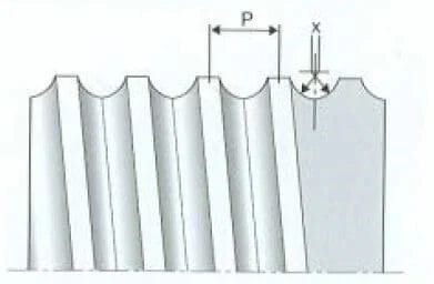
P Pitch, x Radius offset
The Carry ball screw drives from Eichenberger impresses by moving high loads with low energy consumption and is wear-free.
Other special threads
In addition to the standard rolled thread systems listed at the beginning of the article, there are also various special threads with their own profile:
- The lion's heart thread has a flank angle of 53° 8′ and is known as a precision engineering thread; it has since been replaced by the metric basic profile according to DIN 13.
- The E-thread (Edison thread to DIN 49689) is known as a lamp socket thread in every household. Two specially interlocking radii ensure good electrical contact.
- The Thury thread according to Professor Thury from Geneva is a special ultra-fine watch thread.
- The BA threada fine English thread with a flank angle of 47° 30′, is available up to 6mm diameter. It was developed after 1900 for the watch industry and precision mechanics.
- The Swiss NHS thread is another special thread for the watch industry. It has even made the leap to America, although its profile there is defined in inches.
- Special threads for fuel and oil lines often have profiles with better sealing properties.
Determine the accuracy of fit
The accuracy of fit of an external thread in a nut element with internal thread is determined by the following elements:
- Outside diameter (nominal diameter)
- Core diameter
- Gradient
- Flank angle
- Flank diameter
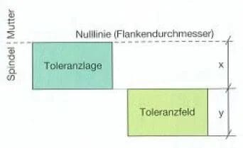
The pitch of standard threads is directly related to the outside diameter (diameter-pitch series). The pitch diameter is important because it represents the tolerance base (zero line) (Fig. 10).
The ISO thread tolerances
As is the case with the tolerance system for fits, the ISO thread tolerances are made up of a specification for the tolerance position and one for the size of the tolerance zone.
The tolerance position is determined by one of the code letters a to h, the size of the tolerance zone is indicated by a number between 3 and 9 (Fig. 10). For better differentiation from the fit tolerances, the number - the size of the tolerance zone - is stated first for the thread, e.g. 6h and not h6. The smaller the number, the more precise the tolerance.
The pitch diameter and the outside diameter of a thread can have different tolerances. For example, M10-4h-6g means that the tolerance of the pitch diameter is 4h and that of the outside diameter is 6g. Narrow tolerances of a thread allow larger tolerances of the corresponding nut element and vice versa.
Tolerance positions a to g are particularly suitable if surface protection (hot-dip galvanizing, electrogalvanizing or chromium plating) with the coating thicknesses commonly used today is planned.
We will be happy to assist you in selecting the right thread. Contact us here.
Measuring methods and measuring equipment
The three-wire test method
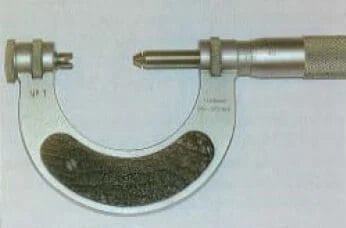
In the three-wire test method, two cylindrical test wires are placed in the threads on one side and one test wire on the opposite side (Fig. 11). The outer distance between the test wires, the test dimension M, is then measured with the flat and parallel test surfaces of a measuring device, e.g. a micrometer, and the pitch diameter d2 of the external thread is determined from this. Two conditions must be met for the test wire diameter: The diameter of the test wires must be large enough to protrude over the thread tips. The test wires must be as close as possible to the theoretical flank diameter so that existing flank angle deviations cannot significantly influence the measurement result. The theoretical measuring wire diameter is determined by calculation.
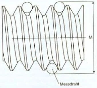
M Mass via measuring wire
Thread measuring and testing
In most cases, the thread is checked with a ring gauge. Only rarely is a micrometer with measuring inserts used. In this case, the thread is measured directly on the thread flank (Fig. 12). The measuring inserts are ground and show the thread flank angle. The measuring tool, a micrometer with holes for the inserts, is available as standard for metric and imperial threads. Gauge rings are used to check the thread tolerance (runout): The good ring gauge must run on the thread, the reject ring gauge must not.
Another test method is the thread gauge (also known as a limit gauge), which is used to check the pitch diameter of a thread. The good side of the thread gauge represents the maximum permissible size and must slide over the test point due to its own weight. The reject side is smaller by the tolerance and represents the smallest dimension and must withstand its own weight. The result is good or bad or reworking is required.
Eichenberger - your service provider right from the start
With Eichenberger, you can implement your individual requirements for a thread drive right from the start of development. Don't hesitate to contact us before you even know what you need. We will be happy to work with you to develop your individual solution for your thread system. Contact one of our experts directly, we will be there for you right from the start.
> Contact us now without obligation and find out more
With state-of-the-art production methods, many years of expertise and a tool inventory of over 1000 rolling tools, we produce rolled screw drives that meet even the most unusual requirements:
- Gradients up to 6 x diameter
- Slope accuracy class G5
- Spindle lengths up to 6 meters
- Spindle diameter from 2 to 160 millimetres
- All standard profiles (M, Tr, UNC, UNF, UNEF, Whitworth)
- Multi-start threads, also as right/left-hand threads
- Steep thread profiles
- Ball screw profiles
- Special profiles
- Screw profiles (special quality and price advantages!)
- Serrations and knurling
- Conical thread
- Threads on prefabricated and/or bulky parts, e.g. also on forged parts
- Freely designed thread geometry
- Responding to customer requirements, e.g. customized nut geometry
Eichenberger leaves nothing to chance and places the highest value on quality. This has been convincing our customers since 1953. See for yourself:
> 100% Swiss Quality
> Thread specialist since 1953
Multi-start threads with pitches up to 6 x diameter, nuts made of plastic or bronze


