Important rolling processes and tools
Specialist topic thread rolling told in an exciting way ... basics, processes, tools, applications of rolled high-tech threads
Various rolling technologies
Several rolling technologies have become established in industrial practice. Even in the early days of thread rolling, a distinction was made between processes that work with round tools and flat tools (flat dies). Sometimes the rolling processes are subdivided according to the number of tools used.
In the following description of the different rolling processes for high-tech threads, we will only deal with general issues.
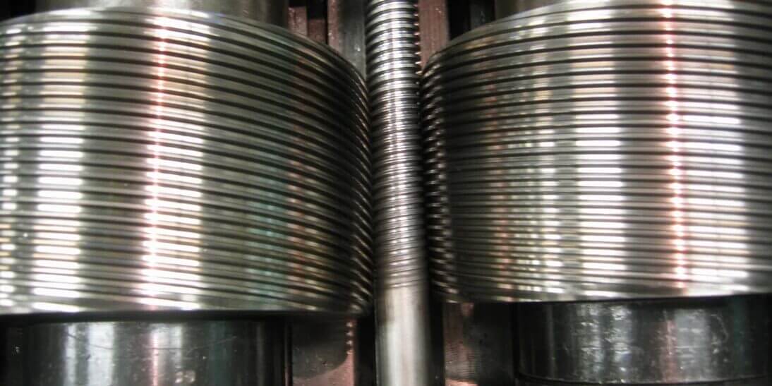
Rolling process with two round tools,
symmetrical or asymmetrical
In the case of thread rolling with two externally profiled tools, the two driven rollers rotate in the same direction. A distinction is made between a symmetrical and an asymmetrical variant. In the symmetrical version, both tools move towards the blank, whereas in the asymmetrical version, one of the (rotating) tools remains stationary while the other moves towards the blank. The major advantage of the symmetrical variant is the significantly longer tool life.
The blank is always located between the rolling tools. If the moving tool touches the (still) stationary blank, it is set in rotation by the very fast build-up of frictional locking. The tool profile then forms a thread in the blank.
Grooving process
Every mechanic is familiar with grooving during turning: The supplied turning tool pierces the blank and forms a predetermined geometry. In the grooving process, the two movable tools move towards the blank and groove it with the profile. The tools have grooves with the pitch angle of the thread to be rolled.
Pitch groove symmetrically into the workpiece
Very precise, but finite threads
The principle of the grooving process allows the production of very precise threads. The disadvantage is obvious: because the blank is not fed, the maximum thread length is limited to the tool length.
The accuracy of the thread largely depends on the tool, which is manufactured in several steps. The tool profile is most often produced by grinding. In order to eliminate the distortion of the heat treatment, grinding only takes place after hardening. The surface finish of the roll profile is decisive for the quality of the threads produced.
Their manufacturers - specialist companies - use high-quality tool steel for the tools. Most manufacturers prefer special alloys, but some also offer tools made from other materials and with different heat treatments on request.
Continuous process
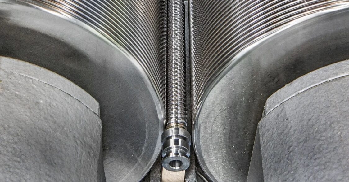
The two tools for the throughfeed process have several grooves without pitch on their circumference, which run in a circle around the tool. The two rollers lying horizontally in the machine are tilted in opposite directions around their horizontal transverse axis, in each case by the pitch angle of the thread to be rolled. If the front end of the right-hand roller is tilted downwards and the left-hand roller is tilted upwards, a right-hand thread is produced and, conversely, a left-hand thread.
to see both pitchless tools
As the tools swivel, the blank also moves forwards in the horizontal axis (parallelogram of forces!). The rotating blank thus runs through the machine - the throughput speed can be influenced by the rotation speed of the rollers.
"Infinite threads"
The advantage of the throughfeed process is that it is (theoretically) possible to produce an infinitely long thread. The length ultimately only depends on the length of the blank. However, a somewhat lower dimensional accuracy must be accepted compared to the grooving process.
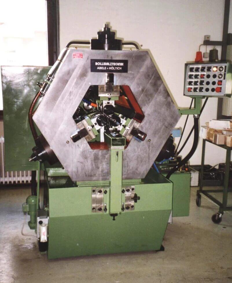
The machine must be equipped with swiveling roller spindles for the throughfeed process with two pitchless tools.
One pair of tools for different core diameters
Another advantage is that the thread manufacturer can roll the same pitch on workpieces of different diameters with a single pair of tools - apart from a few restrictions. However, if very tight thread tolerances are required, it may still be necessary to produce a separate tool for each batch of material.
The choice of material for through-feed tools is the same as for grooving tools. The grooves are applied by grinding and, more recently, increasingly by hard turning with special inserts. Because an axial feed takes place, the tools have three zones with different outside diameters, analogous to the three phases of the rolling process: A run-in zone, a calibration zone and a run-out zone.
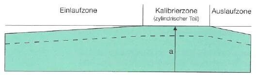
a Diameter of the calibration zone
The transition from the run-in zone to the calibration zone determines whether the tools achieve the required service life. Throughfeed tools from different manufacturers differ relatively greatly in this detail. If "difficult" base materials are to be rolled, it is recommended to seek the advice of the tool manufacturer.
Partially corrected continuous process
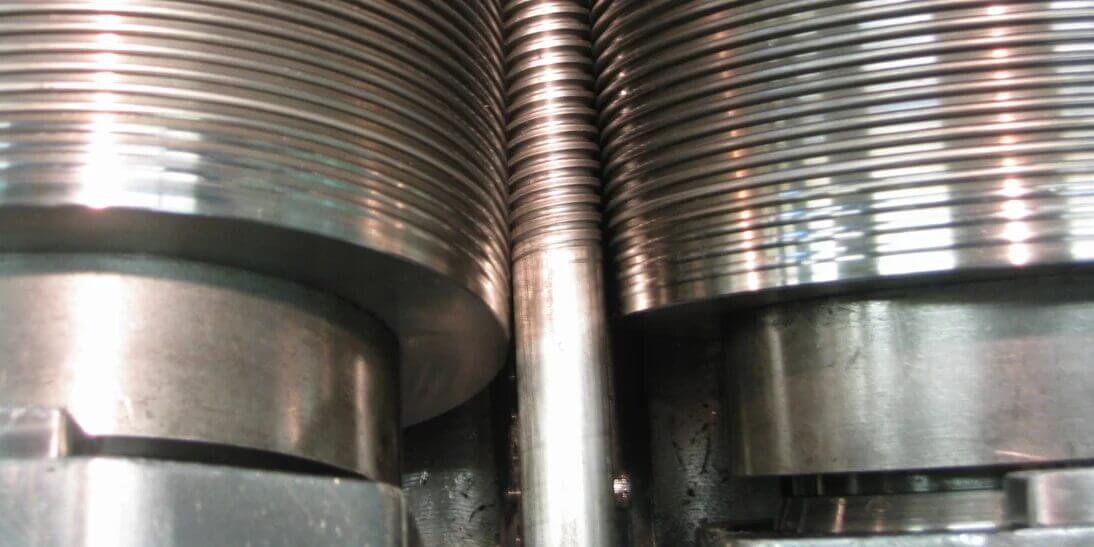
The partially corrected throughfeed process is a combination of the plunge-cut and throughfeed processes. The grooving process contributes the pitch on the tools, while the swivel capability of the rolling spindle was adopted from the throughfeed process. The profile pitch of the tools is not identical to the pitch of the thread to be rolled. The angle difference is compensated by tilting the rolling spindles, as described for the throughfeed method. Thread rolling tools for the partially corrected throughfeed method also have a run-in, calibration and run-out zone.
Large inclines
With the partially corrected pass-through method, considerably greater gradients can be achieved than with the pure pass-through method. An example will illustrate this: The thread must have a lead angle of 15°. However, a rolling spindle for the throughfeed method can be swiveled by 5° at best. To achieve the required 15°, the tools are given a profile pitch of 10° and the missing 5° is set on the machine.
a gradient groove and are also inclined.
The blank undergoes an axial movement during the forming process, as in the continuous process. The service life of the rollers depends to a large extent on the tool design and the material of the blank.
Throughfeed process with corrected tools
The throughfeed process with corrected tools makes it possible to work with a machine without swivel roller spindles in the throughfeed process. However, it is only recommended if no machine with swivel roller spindles is available.
The throughfeed process with corrected tools is similar to the partially corrected throughfeed process. The lead angle of the tool profiles is either larger or smaller than that of the thread. However, unlike the partially corrected throughfeed method, it is not possible to correct the pitch by swiveling the rolling spindles. The disadvantage is therefore that pitch errors must be accepted.
Rolling process with three or more tools
Thread rolling with three or more driven tools is always a method derived from the methods described with two rollers. As a rule, three rollers are used, which are arranged symmetrically around the blank at angles of 120° to each other. As with the plunge and throughfeed method, the blank is gripped centrally by the tools and rotated. The multi-roller principle makes support rulers and holding devices superfluous.
Suitable for pipes and hollow parts
It is mainly used for pipes and hollow parts. The disadvantage is the high investment for the machine and tools.
Supplementary rolling procedures
The most important rolling processes for high-tech threads - especially for threaded spindles - are the grooving process, the through-feed process and the partially corrected through-feed process. In order to provide interested readers with as comprehensive an overview as possible of the thread rolling processes used in industry, further processes with the associated tools are described below, but without any claim to completeness.
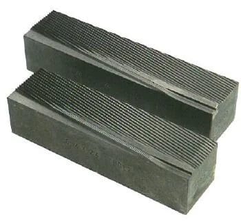
Cross rollers with two flat tools
Cross rolling is characterized by two opposing flat tools (flat jaws) that engage with the rotating blank. During thread rolling, they generally move past the blank in opposite directions. There is also a variant in which one flat die is fixed in the machine while the second flat die - mounted on a slide - moves past the workpiece. This method has found its place in mass production - e.g. of standard screws - and where accuracy requirements are low. It is a standard process, but its possibilities have been exhausted.
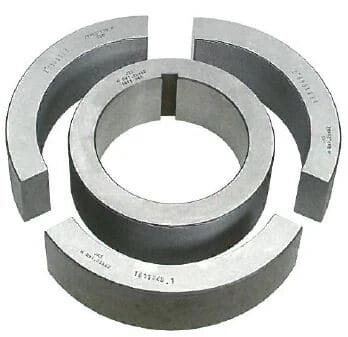
Thread rollers with the segment roller
In thread rolling with the segment roller, three thread segments fixed in the machine body with an inlet and outlet zone press the rotating and passing blank against a rotating thread ring. The advantage of this thread rolling process is the uniform rotary movement of the threaded ring sitting on the driven shaft.
Thread rolls with rolling heads
Thread rolling with rolling heads is a process that is used quite frequently when threads are to be produced on a lathe. Non-driven tools are used. The rotary movement of the blank is generated by the machine tool. This type of production is very economical. Turned parts can be produced completely on automatic machines - including the threads - i.e. without reworking (décolletage).
Thread rolling with thread rolling dies
Due to its compact design, the thread rolling die enables the production of threaded bolts without clamping, even in the tightest of spaces, e.g. in the machining area of a machine tool. The thread length that can be produced is limited by the machine tool. After the rolling process, the thread rolling die must be turned back in the resulting thread.
A distinction is made between adjustable and non-adjustable tools. Adjustable thread rolling dies are set with the aid of a holding device. Thread rolling with adjustable dies has a not insignificant advantage in general mechanical engineering: without special rolling machines, the use of adjustable dies is extremely economical and therefore recommended for small and medium series. In the case of non-adjustable thread rolling dies, it is particularly important to specify the thread tolerances and the material in advance. Non-adjustable thread rolling dies are suitable for larger series.

To the blog overview
Technical principles of thread rolling
Service provider in development
With state-of-the-art production methods, many years of expertise and our tool inventory of over 1000 rolling tools, we produce rolled threads that meet even the most unusual requirements:
- Gradients up to 6 × diameter
- Spindle lengths up to 6 m
- Spindle diameter from 2 to 160 mm
- All standard profiles (M, Tr, UNC, UNF, UNEF, Whitworth)
- Multi-start threads, also as right/left-hand threads
- Steep thread profiles
- Ball screw profiles
- Special profiles
- Screw profiles (special quality and price advantages!)
- Serrations and knurling
- Conical thread
- Threads on prefabricated and/or bulky parts, e.g. also on forged parts
The 9 blogs contain excerpts from the - Library of Technology -, Volume 286, Thread rolls, included.
This book was compiled with the technical support of Kurt Husistein and published by Verlag Moderne Industrie, ISBN 978-3-937889-30-6.
Literature and sources
Kübler, Karl-Heinz, Mages Walter J. Handbook of high-strength screws, 1st ed. Essen: W. Girardet Buchverlag, 1986.
http://www.hp-gramatke.de: Hans-Peters Mathematical-Technical-AlgorithmicA linguistic smorgasbord.Verein Deutscher Eisenhüttenleute (ed.): Werkstoffkunde Stahl, vol. 1 Berlin: Springer, 1984. Apel, Heinz: Gewindewalzen: Kaltverformen von Präzisionsgewinden und Spindeln, Munich: Hanser 1952.
© 2007 All rights reserved by sv corporate media, D-80992 Munich
Illustrations: No. 1, 23-25 RWT Rollwalztechnik GmbH, Engen; No. 2 Photo Deutsches Museum, Munich; No. 3 Musée du tour automatique et d'histoire de Moutier, Moutier (Switzerland); No. 16 Fette GmbH, Schwarzenbek; No. 18 Meinrad Plaz, Staufen (Switzerland); No. 26 Habegger SA, Court (Switzerland); No. 34-36 FBT Fahrzeug- und Maschinenbau AG, Thörigen (Switzerland); No. 37, 38 Schleuniger AG, Thun (Switzerland); No. 39, 40 Max Planck Institute for Physics (Heisenberg Institute), Munich; No. 41 Saurer AG, Arbon (Switzerland); No. 42 Line Tech AG, Glattbrugg (Switzerland); all others Eichenberger Gewinde AG, Burg (Switzerland). Typesetting: abavo GmbH, D-86807 Buchloe. Printing and binding: Sellier Druck GmbH, D-85354 Freising. Printed in Germany 889030.