The library of thread rolling - 6/9
In this blog article you will learn more about the production of rolled threads, the raw material, the phases of thread rolling, the time and duration, the correct temperature and monitoring.
Regardless of the individual processes or variants, thread rolling always involves a wedge-shaped tool geometry that penetrates the raw part material. The tool displaces the material, which flows into the free spaces of the tool contour during the process. The process is completed when either the intended flow height of the material is reached or the tool contour is filled with material.
Raw material
For thread rolling, the raw material must be rotationally symmetrical, i.e. cylindrical with a constant diameter. However, thick-walled pipes and other hollow bodies may also be suitable for thread rolling. However, filigree workpieces such as thin-walled pipes are not suitable for this, as the material flows in all spatial directions if the material thickness changes significantly. The required diameter of the raw part is determined on the basis of empirical values or can be calculated. Two parameters are decisive: the unwinding ratio between the workpiece and the tool and the flow volume of the material required for the intended final shape.
Material requirement: at least 6 % elongation
In principle, any material is suitable for thread rolling provided that it can be plastically deformed at all. In other words, the material must allow an elongation of over 6 % without breaking during the thread rolling process.
Max. 1200N/mm2 Tensile strength
In the information on the maximum permissible tensile strength - e.g. kf0 = 1200N/mm2 - the question of the formability of the material is less important than the question of a reasonable service life of the tool. The lower the tensile strength and the more correct the diameter, the longer the service life of the tool.
It should be noted that the material to be rolled has a significant influence on the forming process, the rolling force applied by the machine and the service life of the tools.
The formability of metal materials is determined by their crystalline structure and chemical composition. For example, the carbon content significantly changes the formability of steels: as the content increases, the possibility of shaping decreases and the tendency to work hardening increases.
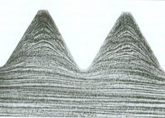
The hardening of the material during deformation must be given special consideration when answering the question of which materials are suitable for thread rolling. Hardening is based on complex plastomechanical processes in the crystal structure and can be demonstrated on the ground cross-section of a rolled thread (Fig. 1). It cannot be emphasized enough that although materials that solidify result in highly resilient components, the rolling process requires special measures and a great deal of experience.
Phases of the thread rolling process
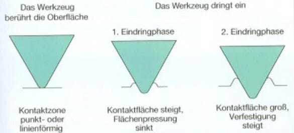
There are three phases during the thread rolling process (see Fig. 2): the preparation phase, in which the tool touches the surface, followed by the first penetration phase and then the second penetration phase, in which the tool penetrates the material. These three phases are described in more detail below.
Preparation phase
At the beginning of the forming process, the wedge-shaped tool touches the surface of the cylindrical workpiece. The contact zone is point-shaped or linear, depending on the geometry of the rolling tool. The contact area of the workpiece with the tool is small at this point, taking into account the elastic properties of the materials. The force applied by the machine therefore leads to a surface pressure that is usually far higher than the strength of the material. In this first rolling phase, the preparation phase, such high compressive stresses are applied to the blank that the material begins to deform plastically.
First penetration phase
In the next phase of the rolling process, the first penetration phase, the wedge-shaped tool profile presses rather slightly into the material. The base material changes its internal structure and hardens according to the described forming mechanisms. In this phase, the contact surface between the tool and the workpiece grows and becomes significantly larger than in the preparation phase. However, as the contact area increases, the surface pressure decreases, meaning that the machine would have to apply a significantly greater rolling force in order to maintain the penetration speed. In most cases, however, the machine is already working at maximum rolling force during the preparation phase. As a result, the penetration speed generally decreases during the penetration process.
Second penetration phase
In the last rolling phase, the second penetration phase, the contact area increases and is therefore significantly larger than in the first penetration phase. The onset of material hardening makes the penetration process even more difficult.
Time sequence for thread rolling
The maximum penetration distance specified by the gaps in the rolling tool is reached at different speeds depending on the material. The continuous decrease in surface pressure while the rolling force of the machine remains constant and the material hardening associated with the forming process have a significant influence on the timing of the penetration process.
In order to obtain evaluable statements on the rolling life of different materials, all material-independent influences, especially the machine parameters and the tool geometry, must be known and coordinated. A more pronounced profile depth and shape increase the rolling life.
Temperature behavior and cooling during thread rolling
The temperature increase results from the external and internal friction during the rolling process and depends directly on the material and the set machine parameters.
Use of a cooling medium
In practice, forming is carried out using a cooling lubricant that flows over the workpiece and the tool. The chemical composition of the coolant and its application parameters are a well-kept secret of the manufacturer, as the resulting differences in quality can be considerable. Particularly with throughfeed machines (more on this in blog 8/9 Continuous process) for the production of threaded spindles with very small pitch tolerances, constant temperature conditions on the workpiece and tool during rolling are of crucial importance. If this is not achieved, undefined lead distortion will occur.
Coolant treatment
To ensure that the temperature conditions remain constant during the rolling process, the machines are equipped with conditioning systems that provide the supplied coolant in a reproducible quantity, temperature and purity. The temperature of the coolant is thus kept constant within a range of ±1.5 °C.
The change in temperature of the workpiece reveals how well the flow process has been achieved. The base material should tend not to heat up or only heat up slightly. The expert knows from experience when to use which medium for cooling.
Monitoring
The rolling process is controlled and monitored in different ways. A distinction is made between production on conventional thread rolling machines, on which around 90% of the rolled threaded parts are produced, and CNC production (Computerized Numerical Control), on which only less than 10% are produced. The measuring and monitoring systems used in practice today record variables whose changes over time influence the forming process. The measured parameters can be forces, torques or power.
Workpiece measurement
In order to obtain an optimum workpiece in conventional production, the pre-machining diameter on which the deformation is based must be precisely maintained. For this purpose, the workpieces are measured several times at suitable points in the production process.
If the workpiece is machined on a CNC machine, the penetration depth and penetration speed of the tool into the workpiece are specified via the respective user interface and stored in a program. The control system continuously checks the values during machining and adjusts accordingly. This makes it possible to compensate for homogeneity differences in the material that cause the machine to be loaded differently.
Image processing systems and mechanical measuring equipment
In industrial practice, image processing systems or mechanical measuring devices are used for this purpose. These can also be used to evaluate the workpieces after processing.
Rolling force detection systems
Décolletage systems, which are used to produce small and very small parts for the watch industry in series of millions, are a special case. In these special systems, the material to be processed is fed fully automatically as bar blanks. The forming process in the grooving process is checked and evaluated using rolling force detection systems. These systems record the force or torque curve over a defined distance or over a specified period of time. The two recorded parameters are then evaluated. This results in envelope curves that must not be exceeded or undercut.
Another option for automated monitoring is the definition of windows through which the force progression must pass. If the workpieces do not meet these criteria, they are rejected. These procedures provide indirect information as to whether the pre-machining diameter or the material met the specifications. They can even signal the onset of tool breakage.
Find out in the next article why the rolling process must be stopped before the intended shape is reached and how the expert can recognize this.
> The Library of Thread Rolling Blog 7/9
Eichenberger - your service provider right from the start
With Eichenberger, you can implement your individual requirements for a thread drive right from the start of development. Don't hesitate to contact us before you even know what you need. We will be happy to work with you to develop your individual solution for your thread system. Contact one of our experts directly, we will be there for you right from the start.
> Contact us now without obligation and find out more
With state-of-the-art production methods, many years of expertise and a tool inventory of over 1000 rolling tools, we produce rolled screw drives that meet even the most unusual requirements:
- Gradients up to 6 x diameter
- Slope accuracy class G5
- Spindle lengths up to 6 meters
- Spindle diameter from 2 to 160 millimetres
- All standard profiles (M, Tr, UNC, UNF, UNEF, Whitworth)
- Multi-start threads, also as right/left-hand threads
- Steep thread profiles
- Ball screw profiles
- Special profiles
- Screw profiles (special quality and price advantages!)
- Serrations and knurling
- Conical thread
- Threads on prefabricated and/or bulky parts, e.g. also on forged parts
- Freely designed thread geometry
- Responding to customer requirements, e.g. customized nut geometry
Eichenberger leaves nothing to chance and places the highest value on quality. This has been convincing our customers since 1953. See for yourself:
> 100% Swiss Quality
> Thread specialist since 1953
Technical principles of thread rolling
Literature and sources
Apel, H. (1952). Thread rolling: Cold forming of precision threads and spindles. Hanser.
DeWiki (2022, August 3). Lexicon thread. https://dewiki.de/Lexikon/Gewinde
Kübler, K. & Mages W.J. (1986). Handbook of high-strength bolts, (1st ed.). Girardet.
Peters, H. (2003). Mathematical-technical-algorithmic-linguistic smorgasbord. http://www.hp-gramatke.de
Trösch, B. & Husistein, K. (2007). Library of Technology -, Volume 286, Thread Rollers. Modern industry.
Verein Deutscher Eisenhüttenleute (1984) (ed.). Materials science of steel, vol. 1, Springer,
Wikipedia (2022, August 3). ISO metric thread. https://de.wikipedia.org/wiki/Metrisches_ISO-Gewinde
© 2007 All rights reserved by sv corporate media, D-80992 Munich http://www.sv-corporate-media.de
Illustrations: No. 1, 23-25 RWT Rollwalztechnik GmbH, Engen; No. 2 Photo Deutsches Museum, Munich; No. 3 Musée du tour automatique et d'histoire de Moutier, Moutier (Switzerland); No. 16 Fette GmbH, Schwarzenbek; No. 18 Meinrad Plaz, Staufen (Switzerland); No. 26 Habegger SA, Court (Switzerland); Nos. 34-36 FBT Fahrzeug- und Maschinenbau AG, Thörigen (Switzerland); No. 37, 38 Schleuniger AG, Thun (Switzerland); No. 39, 40 Max Planck Institute for Physics (Heisenberg Institute), Munich; No. 41 Saurer AG, Arbon (Switzerland); No. 42 Line Tech AG, Glattbrugg (Switzerland); all others Eichenberger Gewinde AG, Burg (Switzerland). Typesetting: abavo GmbH, D-86807 Buchloe. Printing and binding: Sellier Druck GmbH, D-85354 Freising. Printed in Germany 889030.


